Home > Resources > Gaming Headset Guide
How Should OEM Buyers Validate Antenna Integration in a 2.4GHz Wireless Gaming Headset?
A buyer-focused engineering guide to validating the PCB, antenna, enclosure, internal layout and receiver as one 2.4GHz RF system before gaming headset design freeze and mass production.
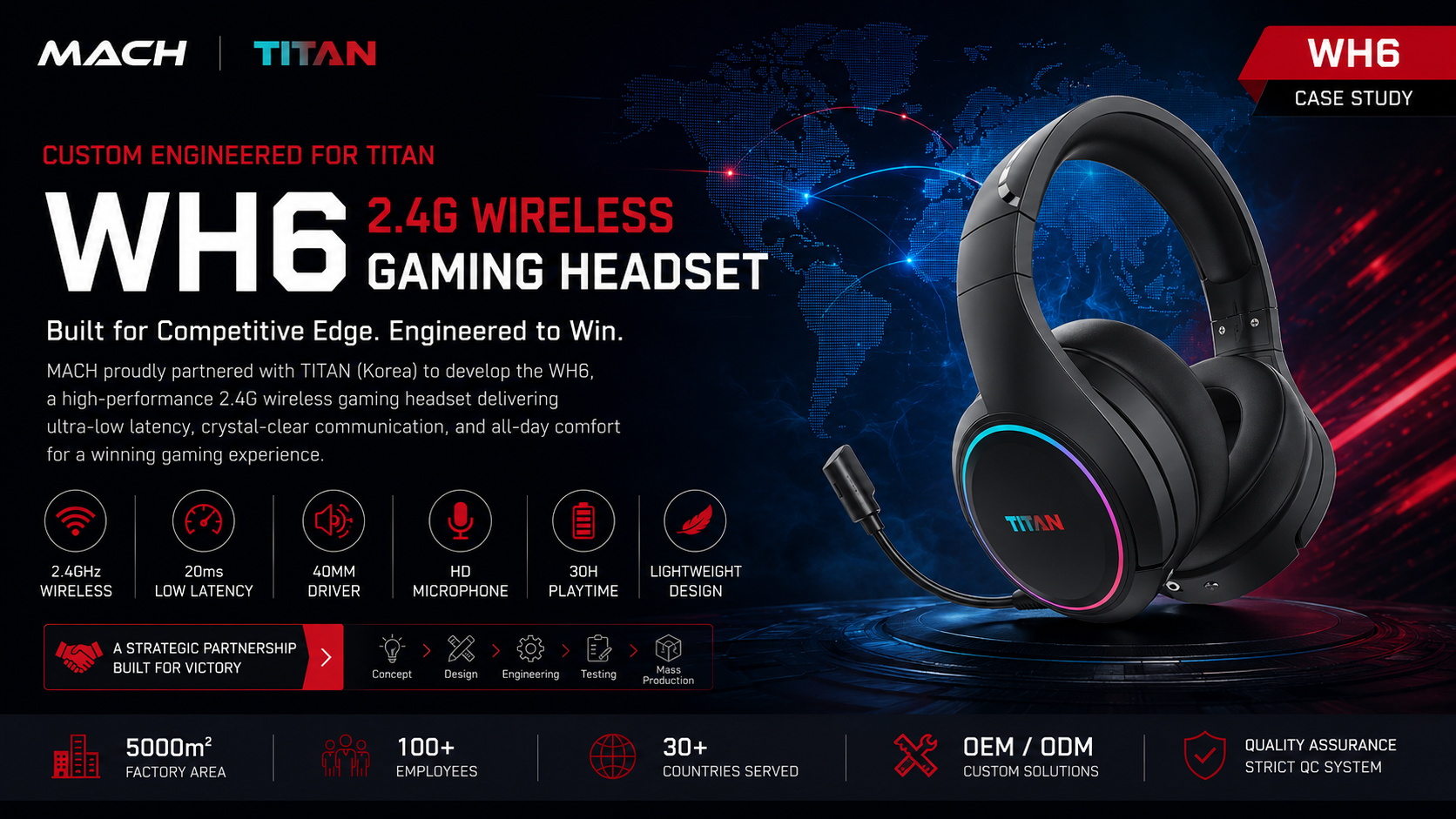
A reliable 2.4GHz gaming headset cannot be validated by checking the RF module or antenna as isolated parts. OEM buyers should evaluate the complete RF system: the PCB revision, antenna location, enclosure, nearby structural and electronic parts, battery position where relevant, receiver-side hardware, and the firmware or RF configuration used by the sample. The purpose is to confirm that the production-intent assembly behaves as one controlled wireless link before the design is frozen.
This matters because a wireless solution that works on an open engineering board is not yet a validated headset. Mechanical integration changes the environment around the antenna, while an unrecorded receiver or firmware revision can make two outwardly identical samples technically different. Buyers therefore need revision traceability, a defined validation plan and explicit re-test triggers rather than a single statement that the antenna has been checked.
What Does Antenna Integration Mean in a Gaming Headset?
Antenna integration is the engineering work required to make the antenna, PCB, enclosure, internal layout and receiver operate as one defined RF system inside the finished headset.
Selecting a radio chipset and naming an antenna type do not establish finished-product wireless performance. In an OEM headset, the transmitting and receiving paths depend on the released hardware configuration and on how those parts are positioned within the product. The antenna is therefore not an accessory added after industrial design; it is part of the architecture that industrial design and mechanical engineering must accommodate.
The receiver also belongs to the RF link, even though this article is not a receiver specification guide. A headset-side review cannot prove that an unmatched or revised receiver will behave identically. Buyers should confirm which receiver revision was paired with which headset revision and keep that relationship visible through prototype validation, pilot production and final release.
Why Antenna Performance Can Change After Industrial Design
Industrial design can change the physical environment around the antenna, so the production-intent assembly requires its own engineering review even when the underlying wireless platform is mature.
An engineering board is evaluated without the full geometry of a headset. The production design adds an earcup shell, structural supports, buttons, cables, lighting parts, a battery and other components. Their materials and positions may alter the antenna's operating environment or limit the placement originally assumed by the RF design. The correct procurement response is not to predict the result from appearance; it is to identify which changes require review and validate the representative build.
Enclosure geometry matters because the antenna must fit inside a constrained three-dimensional space while maintaining the intended product shape, controls and comfort. A cosmetic revision can become an RF revision when it moves an internal bracket, changes the space available around the antenna or requires the PCB to shift. Likewise, a new material or finish should be assessed for engineering impact instead of being approved solely from a color sample.
Internal layout changes can be easy to miss in a commercial approval process. A battery with a different outline, a relocated connector, a revised cable path or a changed lighting assembly may leave the exterior unchanged. That is why the approved appearance sample and the approved RF configuration should reference the same mechanical and electrical revisions. These changes do not prove a failure, but they should trigger engineering impact review.
What Real OEM Projects Teach Us About Antenna Validation
MACH's public WH6, WH6-BT and X3 case studies show that RF stability and antenna work belong inside wireless headset development, alongside structure, tooling, sampling and production control.
The WH6 Korea OEM case publicly describes a 2.4GHz wireless headset project that included RF stability, antenna tuning and wireless range checks. It also identifies PCB and RF support, tooling follow-up, sample validation, trial production and QC as parts of the wider project. These statements support a buyer lesson: antenna activity must remain connected to the exact product revision moving through development.
The WH6-BT Korea OEM case adds Bluetooth to the product architecture and publicly refers to RF stability and antenna review. The existence of more than one wireless mode increases the importance of identifying the mode, hardware and configuration represented by each validation record. The public case does not disclose a specific test chamber, interference setup or measured antenna result, so this guide does not attribute those activities or outcomes to that project.
The X3 Spain OEM case similarly lists RF stability and antenna validation among the development requirements for a 2.4GHz wireless headset. Its public product material also shows the headset and Type-C dongle as parts of one usable system. This supports treating both ends of the proprietary wireless link as a matched configuration without turning the case into evidence for unreported performance values. These cases provide project context, not a universal test standard.
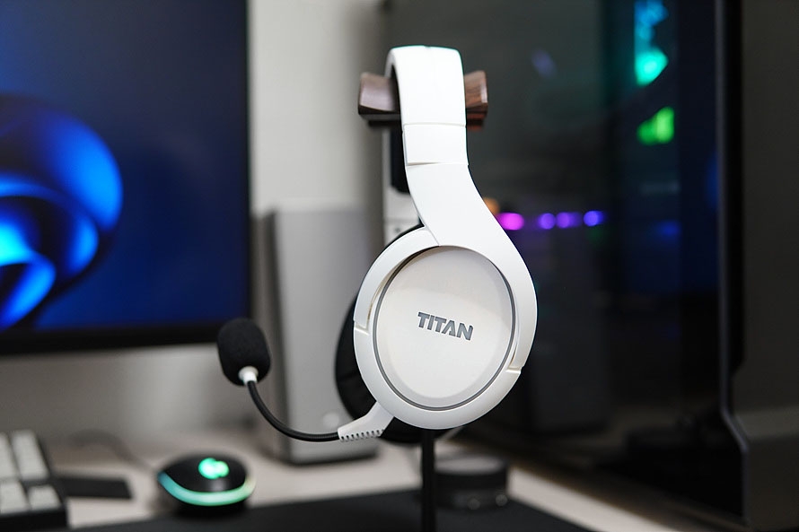
From PCB to Enclosure: Validating the Complete Antenna Integration
The most useful validation workflow follows the design from electrical architecture through mechanical integration and records which complete headset-and-receiver configuration was actually evaluated.
Start with the RF architecture and the intended product layout. The engineering team should identify the headset PCB revision, radio section, proposed antenna location and matched receiver architecture. At this stage, the buyer does not need to prescribe an antenna solution without the supplier's engineering input. The buyer does need confirmation that the architecture supports the intended product modes and that the selected layout leaves a defined integration path before tooling decisions make changes expensive.
Next, review antenna position in the mechanical model. The review should show where the antenna sits relative to the earcup shell, PCB, battery, cables, structural features and other major internal parts. Its purpose is to expose dependencies. If industrial design later moves one of those elements, the change can be traced back to the integration review rather than being treated as an unrelated cosmetic revision.
Mechanical integration then converts the proposed position into an assembly that can be built repeatedly. Confirm the relevant locating features, assembly orientation and any production instruction needed to preserve the intended position. A prototype that works only because a technician manually arranged an internal part is not a sufficient reference for repeatable production. The validation sample should represent the planned structure closely enough for the result to inform design freeze.
Enclosure validation asks whether the assembled shell, material direction and internal arrangement are compatible with the intended RF design. This is an engineering evaluation, not a claim that every cosmetic option changes performance. The important control is that a revised enclosure or internal structure is not silently substituted after the representative sample has been approved.
Receiver-side coordination follows in parallel. Record the receiver hardware revision, connector format and paired firmware or configuration that belong to the validation sample. Host compatibility, receiver packaging and replacement pairing are separate specification topics, but the antenna-integration record should still establish which receiver completed the tested RF link. Without that match, a result cannot be confidently assigned to the retail configuration.
Prototype validation should use a clearly identified sample and agreed evaluation conditions. The public MACH cases confirm RF stability and antenna-related work but do not publish one universal method, threshold or distance. Buyers should therefore ask the supplier to state what was evaluated, which revisions were used, what result was observed and what limitations remain. The evidence may take different forms depending on the project; the requirement is traceability and decision usefulness, not a particular report template claimed by this article.
Before design freeze, reconcile the validation record with the released bill of materials, drawings, firmware identification and receiver revision. Any unresolved mismatch should be closed or explicitly excluded from the approval. After freeze, use predefined re-test triggers so that engineering can assess whether a change invalidates all, part or none of the earlier evidence. This creates a controlled path from prototype learning to production release without pretending that one early sample proves every future variant.
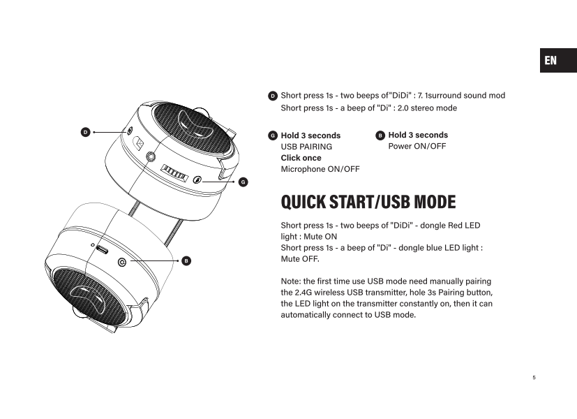
Antenna Integration Validation Matrix
A buyer-readable matrix connects each design element to the evidence needed at design freeze and to the changes that should trigger engineering review.
Use the matrix as a project-control tool, not as a universal pass/fail standard. The supplier's RF and electrical teams should define the appropriate validation method for the actual architecture. Procurement and product teams can then use the matrix to prevent a tested revision from being replaced by a different production configuration without review.
| Design Element | Why It Matters | What the Buyer Should Confirm | When to Re-Test or Review |
|---|---|---|---|
| PCB revision | Defines the implemented radio circuit and physical layout | Revision ID matches the evaluated sample and release file | After a PCB layout or RF-circuit revision |
| Antenna location | Establishes the antenna's position inside the assembled product | Location and orientation are documented in the representative build | After relocation, orientation or retention changes |
| Enclosure and material | Creates the final physical environment around the antenna | Released shell and relevant material direction match the sample | After geometry, material or internal-surface revisions |
| Internal structure | Brackets, cables and assemblies can change nearby geometry | Major internal parts and assembly route match the reviewed layout | After structural or cable-routing changes near the RF layout |
| Battery and component layout | A layout revision can change the production-intent assembly | Component positions relevant to the review are revision controlled | After size, position or mounting changes |
| Receiver hardware | Completes the proprietary headset-to-host wireless link | Receiver revision is matched to the evaluated headset | After receiver PCB, antenna or radio revision |
| Firmware or RF configuration | Determines which implemented configuration the sample represents | Build or configuration identity is recorded where applicable | After changes with potential RF-link impact |
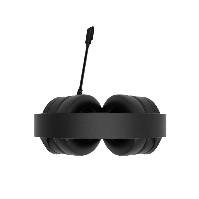
Antenna Integration Validation vs RF Range Testing
Integration validation evaluates whether the product design forms a controlled RF system; range testing evaluates the completed system's connection performance in defined scenarios.
The two activities overlap in subject matter but support different decisions. Antenna integration validation belongs earlier in design control and asks whether the electrical and mechanical implementation is suitable for release. It focuses on revision matching, antenna position, enclosure effects, internal layout and the complete headset-receiver configuration.
Buyers should keep the records connected but separate. Use the antenna-integration file to define what was built, and use the RF range plan to define where and how finished performance was checked. MACH's existing RF Range Validation Guide covers straight-line, office and receiver-position scenarios in greater detail.
| Decision Area | Antenna Integration Validation | RF Range Testing |
|---|---|---|
| Primary question | Is the production-intent RF design integrated and controlled? | How does the finished configuration perform in defined scenarios? |
| Main inputs | PCB, antenna, enclosure, layout, receiver and configuration revisions | A defined finished sample, placement, environment and operating state |
| Main output | Design evidence and re-test triggers for release | Observed connection behavior under stated conditions |
| Best timing | Before design freeze and after relevant design changes | On representative samples and production-controlled configurations |
When Should Antenna Validation Be Repeated?
Any change that may alter the RF implementation or the physical environment around it should trigger an engineering impact review, which determines the appropriate level of re-validation.
A PCB revision is an obvious trigger when it changes the radio layout, antenna connection or nearby circuitry. An antenna relocation or orientation change also deserves review, even if it solves a mechanical assembly issue. The earlier record applies to the earlier configuration; it should not automatically be carried forward merely because the product name is unchanged.
Mechanical changes can be less obvious. Revisions to the earcup shell, internal bracket, cable route, lighting assembly, battery position or another nearby component may require assessment. Use measured language: such changes may require additional validation, and the responsible engineering team should determine the scope. This avoids treating every visual change as a failure while still protecting the approved RF design.
Receiver hardware and applicable firmware or RF-configuration changes should be evaluated as system changes. A new receiver housing alone may or may not matter, but a receiver PCB, antenna or radio revision changes the other end of the link. Similarly, a firmware label is useful only when the team knows whether the changed functions can affect the RF behavior being approved.
Define re-test triggers before release so that a component substitution or materially different variant receives an engineering decision rather than inheriting evidence automatically.
What Evidence Should an OEM Buyer Request Before Design Freeze?
Request enough evidence to identify the RF architecture, tested revisions, validation decision and future re-test conditions without assuming that every supplier uses the same document format.
First, ask for configuration identity. The record should connect the headset PCB, mechanical build, antenna position, receiver revision and relevant firmware or RF configuration. Photographs can support identification, but photographs alone rarely establish hidden PCB or firmware revisions. A short configuration table is often more useful than a polished presentation with no traceable sample ID.
Second, ask what the validation was intended to establish. Was the activity an antenna-position review, a design comparison, a functional RF check or finished-product range validation? Record the method and result at the level actually performed. Do not convert an engineering review into a certification claim or infer an unpublished measurement from a general statement that RF stability was considered.
Finally, record re-test criteria and ownership. Certification planning can run alongside this work, but certification does not replace project-specific antenna validation, and validation does not establish market certification.
- Confirmed RF architecture and connection modes
- Headset PCB revision and receiver hardware revision
- Antenna location and orientation review
- Mechanical and enclosure revision identification
- Relevant internal component layout recorded
- Firmware or RF configuration identified where applicable
- Production-representative sample or declared limitations
- Validation purpose, conditions and observed result
- Approval decision and unresolved actions
- Engineering review and re-test triggers
Before Approving a 2.4GHz Gaming Headset Design Freeze
Design freeze should apply to a defined headset-and-receiver configuration supported by traceable antenna-integration evidence.
- RF architecture confirmed
- Antenna position confirmed
- PCB revision frozen
- Enclosure and relevant material revision frozen
- Major internal component positions reviewed
- Headset and receiver versions matched
- Applicable firmware or RF configuration identified
- Validation completed on a representative sample
- Any sample limitations explicitly recorded
- Re-test triggers defined before release
Prepare an RFQ That Allows Engineering Evaluation
A useful RFQ gives the supplier enough product, platform and design information to evaluate the RF architecture before making commitments about the final headset.
Send the target market, intended users, target platforms and required connection modes. Explain whether the project will use an existing headset platform, a modified platform or a new industrial design. If the PCB or wireless solution is already defined, provide its current revision and identify which elements are fixed versus open to supplier recommendation.
Include the industrial-design status, expected enclosure or material changes, receiver requirements, customization scope and intended certification markets. Share the project timeline, but separate requested dates from validated engineering lead time. If samples already exist, identify their PCB, mechanical, receiver and firmware revisions so the supplier can determine whether they are useful references.
The supplier evaluation should explain the proposed integration path, validation stages, evidence needed for design freeze and change-control responsibilities. This gives the buyer a stronger basis for comparing OEM partners than a generic claim about wireless experience or an isolated chipset specification.
Discuss Your 2.4GHz Gaming Headset Project
Share your target platforms, connection modes, industrial-design status and current headset and receiver requirements for an OEM engineering evaluation.
Request OEM Engineering EvaluationFrequently Asked Questions
What is antenna integration in a wireless gaming headset?
It is the integration of the antenna with the PCB, enclosure, internal layout, receiver and applicable configuration. Buyers should approve the complete production-intent assembly.
Is antenna validation the same as RF range testing?
No. Integration validation evaluates the implemented RF design. Range testing observes a finished configuration under defined distance, placement and operating conditions.
Can an enclosure change affect gaming headset antenna validation?
It may. Geometry, material or internal changes can alter the antenna's environment, so engineering should evaluate whether re-validation is needed.
Should antenna validation be repeated after a PCB revision?
Yes, when engineering identifies RF impact. Changes to the radio layout, antenna connection or nearby circuitry should not inherit earlier evidence automatically.
Does the receiver need to be evaluated with the headset?
Yes. The receiver completes the proprietary link, so its hardware and applicable configuration should be matched to the evaluated headset.
When should antenna integration validation happen in an OEM project?
Begin while PCB and mechanical layouts can still be coordinated, then validate a production-representative prototype before design freeze.
Can regulatory certification replace antenna performance validation?
No. Certification and development validation serve different decisions. Neither automatically replaces the other.
What evidence should a buyer request before approving tooling?
Request revision identification, validation purpose, conditions, observed result, open issues and re-test triggers. The report format can vary by project.
Does a mature 2.4GHz headset platform eliminate antenna integration work?
No. It can reduce uncertainty, but enclosure, layout, receiver and configuration changes still require revision-specific assessment.
What should buyers send with a 2.4GHz gaming headset RFQ?
Provide markets, platforms, connection modes, design status, defined solution and receiver requirements, customization scope, certification markets, timeline and existing sample revisions.
Related Resources
Need OEM/ODM gaming audio solutions?
Contact MACH Industry to discuss your gaming headset, gaming earbuds, or private-label audio project.
Contact MACH Industry